Overview
(All the photos available to this subject)
In my master thesis I built a thermostatic unit for
EPR with biological samples.
The controlled temperature range was 15oC to 65oC in
steps of 5/100 K.
The temperature stability was as good as ±1/100 K.
The whole setup (apart from the EPR spectrometer) constisted
of a regulation unit, the thermostatic fluid circulation
and temperature measuring unit.
- The thermostatic fluid circulation consisted of
- a reservoir,
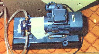
- a pump (photo),
- a water cooling unit (photo),
- two regulated heater stages,
- and the sample holder (photo).
- The regulation unit constisted of
- an NTC sensor (photo),
- a PID regulator for the main heater stage,
- a PI regulator for the pre-heater stage (photo),
- several security NTCs,
- and a special device to prevent excessive temperature
over-/under-shooting and speed up bigger temperature steps.
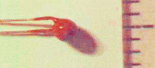
- The temperature measuring unit consisted of a Pt1000 (a "Pt100"
with 1000 Ohms (photo)),
a current source, a device to invert the
current through the Pt1000 and DMV.
The thermostatic fluid circulation
The total volume was about 1000 ml. The circulating fluid was
Silicon oil. The pump was an ordinary one for hydraulics. There was
an ordinary car fuel filter after the pump to make sure no magnetical
impurities would reach the cavity. A water cooling unit decreased the
oil temperature in order to enable the temperature regulation by
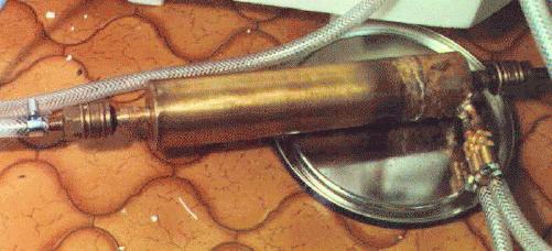
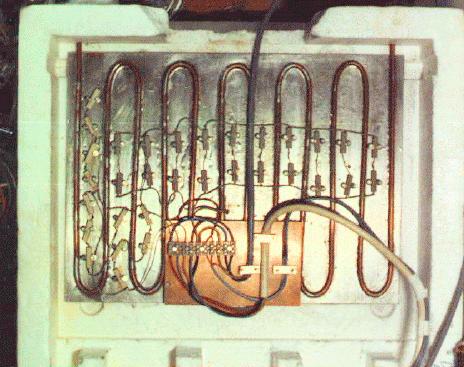
heating. Next was the pre-heater (photo),
which should aproximate the final
temperature. It consisted of a copper plate with the tubing for the oil
attach to it and 5 W resistors distributed on it. The main stage
of the heater was a 2 W resistor in an acrylic block together
with the NTC (photo) of the regulator and
the Pt1000 for the temperature measurement
(photo), all distributed in an
apropriate distance (important!) (photo).
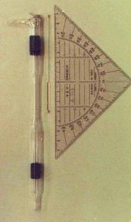
Finally, the silicon oil reached the sample holder, which was built
with glas with an insert for a sample (photo).
The regulation unit
(front view,
rear view and
top view)
The sensor (NTC) was placed in a Wheatstone-Bridge with metal resistors
and separated stabilized power supply. The "bridge-difference" is used
also to manipulate the PID. Namely, the capacitor is shorten for bigger
temperature changes, which limits over-/undershooting.
A PID regulator does the main work. It controls the main heater stage
with a power between 5 and 80 W. A second PI regulator drives
the pre-heater stage. It doesn't look at the Wheatstone-Bridge but
on the output of the main heater stage and trys to keep it in
the middle of the range of the main heater. The power stage of
the PI regulator drives two heaters. The one is a two state heater
of 165 W, which is switched one when the other one, a
continous heater, hits his maximum power of 10 to 240 W. When
the 165 W are switch on, this continous heater is driven down
to about 75 W in order to keep the total power of the pre-heater
stage constant.
NTCs are placed close to the resistors of the heater to sense overheating
and cutting the overall power. This is necessary since overheating would
happen on leakage of the circuit.
The temperature measuring unit
The temperature measuring unit consisted of a Pt1000 (a "Pt100"
with 1000 Ohms), a current source, a device to invert the
current through the Pt1000 and DMV.
Inverting the current through the Pt1000 enables to cancel the
error due to the thermoelectric effect.
Remote control of the regulator
The control unit had a analog interface for remote control, enabling
setting the temperature with a computer.
Maretzek, António F.